Inventory
The Inventory section allows you to add/edit/delete network switches and SoftGates. Initial setup of a Netris managed network is a three part process:
Create Inventory Profiles
Adding Switches
Adding Softgates
Inventory Profiles
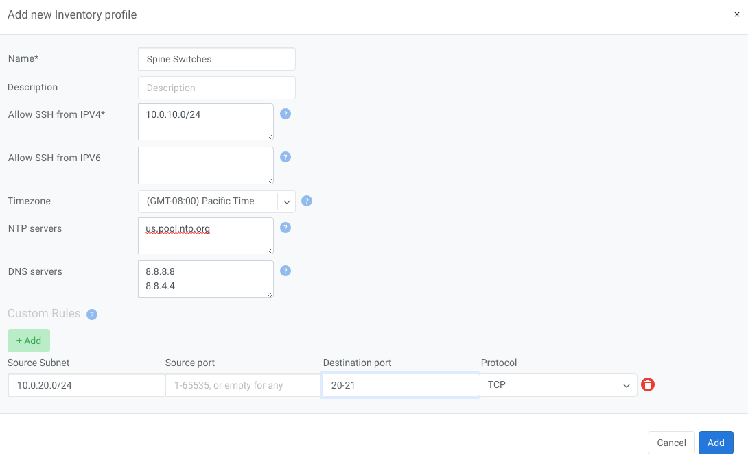
Inventory profiles allow security hardening of inventory devices. By default all traffic flow destined to switch/SoftGate is allowed. As soon as the inventory profile is attached to a device it denies all traffic destined to the device except Netris-defined and user-defined custom flows. Generated rules include:
SSH from user defined subnets
NTP from user defined ntp services
DNS from user defined DNS servers
Custom user defined rules
Name |
Profile name |
Description |
Free text description |
Allow SSH from IPv4 |
List of IPv4 subnets allowed to ssh (one address per line) |
Allow SSH from IPv6 |
List of IPv6 subnets allowed to ssh (one address per line) |
Timezone |
Devices using this inventory profile will adjust their system time to the selected timezone. |
NTP servers |
List of domain names or IP addresses of NTP servers (one address per line). You can use your Netris Controller address as an NTP server for your switches and SoftGate. |
DNS servers |
List of IP addresses of DNS servers (one address per line). You can use your Netris Controller address as a DNS server for your switches and SoftGate. |
Example: In this example Netris Controller is used to provide NTP and DNS services to the switches (common setup).
Adding Switches
Every switch needs to be added to the Netris Controller inventory. You can add new devices with the following process:
Navigate to Net→Inventory
Click the Add button
Fill in the fields as described below
Click the Add button
Add Inventory Fields - Switch¶ Name
Name of the device
Owner Tenant
Owner tenant of the device
Description
Description of the device
Type
There are 3 types of devices that users can add/edit - Switch/Softgate/Controller. Other types are added automatically when creating services like ROH
NOS
Operating system of the device; applicable for switches only
Site
Site where the devices reside
AS Number
Private AS number of the device; applicable for switches only; recommended to be assigned automatically
Profile
Inventory profile for current device. Profiles are used for security hardening the devices
Main IP address
Main loopback IP address for the device. Can be configured manually or assigned automatically from subnet with loopback purpose defined for current site.
Management IP address
Management IP address for the device. Can be configured manually or assigned automatically from subnet with management purpose defined for current site. This IP address is configured on the out-of-band management interface of the device.
MAC address
MAC address of the device; applicable for switches only
Preliminary port count
Used for definition of topology. When the device registers with the controller the real ports are synced with inventory
Add Link
Provides functionality to define the connections between devices; mandatory for Switch and Softgate physical interconnections
Example: Add a new Switch.
Note
Repeat this process to define all your switches.
Adding SoftGates
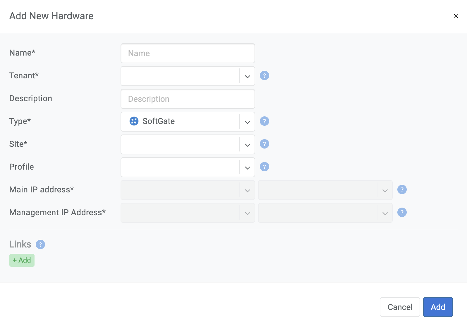
Every SoftGate node needs to be added to the Netris Controller inventory. To add a SoftGate node:
Navigate to Net→Topology
Click Add
Fill in the fields as described below
Click the Add button
Name |
Descriptive name |
Owner Tenant |
Tenant(typically Admin); who administers this node |
Description |
Free text description |
Hardware Type |
Select SoftGate |
Site |
The data center where the current SoftGate node belongs. |
Inventory Profile |
Profile describing the timezone; DNS; NTP; and Security features |
IP Address |
IPv4 address for the loopback interface |
Management IP address |
IPv4 address for the out of band management interface |
NFV Node Port |
A physical port on a spine switch where the SoftGate node’s first SmartNIC port is connected. Typically each spine switch has one SoftGate node connected to it. |
+NAT address |
Public IP addresses to be used as global IP for SNAT/DNAT. (check Enabling NAT section of Network Policies chapter) |
+NAT address pool |
Public IP address subnets to be used as rolling global IP addresses for SNAT. (check Enabling NAT section of Network Policies chapter) |
Example: Adding a SoftGate Node to Topology.
Viewing Inventory
Inventory Listing shows also Heartbeat and monitoring statuses of each device.
Heartbeat - Shows the status of device reachability. Health - Shows number of successful and failed checks on the device.
Note
You can also add new devices in the Topology view.
Topology Manager
The topology manager is for describing and monitoring the desired network topology. Netris Switch Agents will configure the underlying network devices according to this topology dynamically and start watching against potential failures.
Adding Links
To define the links in the network:
Right-click on the spine switch
Click Create Link
Select the From Port and the To Port
See the example below:
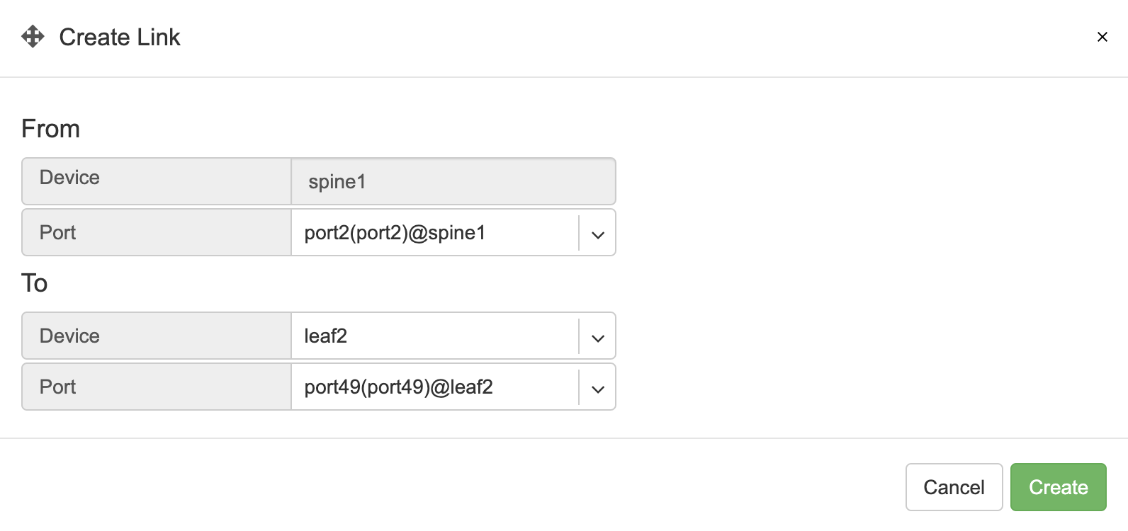
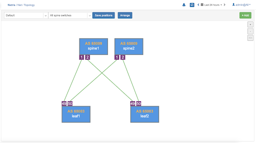
Once the links have been defined, the network is automatically configured as long as physical connectivity is in place and Netris Agents can communicate with Netris Controller.
Tip
You can drag/move the units to your desired positions and click “Save positions”.
Hairpin Links (Nvidia Cumulus only)
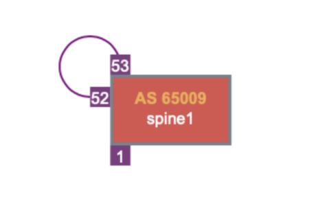
With Nvidia Cumulus Linux only, we need to loop two ports on spine switches (hairpin cable) in the current release, usually two upstream (higher capacity) ports. We are planning to lift this requirement in the next Netris release (v2.10).
To define what ports will be used as a hairpin, navigate to Net→Switch Ports, or right-click on the spine switch, click Ports in Net–>Topology.
Example: Accessing Switch Ports from Net→Topology
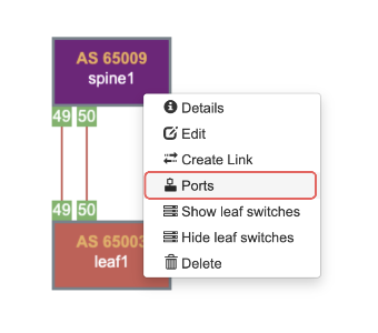
For each spine switch, find the two ports that you are going to connect (loop/hairpin) and configure one port as a “hairpin l2” and another port as “hairpin l3”. The order doesn’t matter. The system needs to know which ports you have dedicated for the hairpin/loop on each spine switch. (do not do this for non-Cumulus switches) | Example: Editing Switch Port from Net→Switch Ports.

Example: Setting port types to “hairpin l2” and “hairpin l3”.

Screenshot: Hairpin visualized in Net→Topology
